Image:2-bit ALU.png
From Wikipedia, the free encyclopedia
Size of this preview: 565 × 599 pixels
Full resolution (2,042 × 2,166 pixels, file size: 51 KB, MIME type: image/png)
| | This is a file from the Wikimedia Commons. The description on its description page there is shown below.
|
[[Category:]]== Summary ==
| Description |
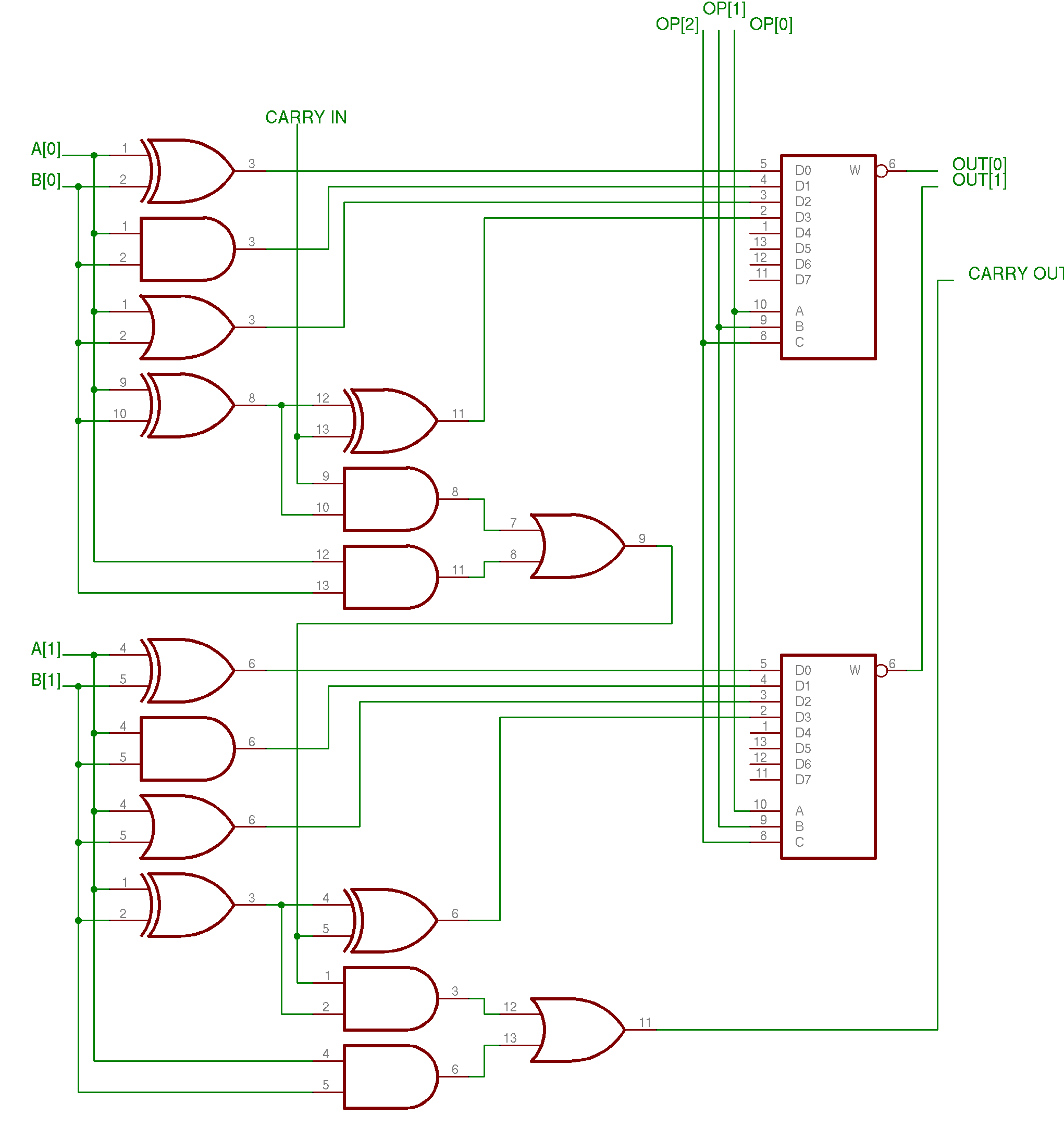
English: A simple example arithmetic logic unit (ALU) that does AND, OR, XOR, and addition.
|
|---|---|
| Source |
English: Own work created with Eagle by Cadsoft
|
| Date | |
| Author | |
| Permission (Reusing this image) |
see below |
[edit] EN
This ALU is a 2-bit ALU with two inputs (operands) named A and B: A[0] & B[0] is the least-significant bit and A[1] & B[1] is the most-significant bit
Each bit of this ALU is identical with the exception of the handling of the carry bit. The handling of one bit is explained below.
The A & B inputs lead into the four gates on the left (from top to bottom): XOR, AND, OR, and XOR. The top three gates perform XOR, AND, and OR operations on A & B. The last gate is the initial gate into a full adder.
The final step to each bit is the multiplexer at the end. The 3-bit OP input (from the control unit) determines which of the functions is outputted:
- OP = 000 → XOR
- OP = 001 → AND
- OP = 010 → OR
- OP = 011 → Addition
Clearly, the last four inputs of the multiplexer are free for other functions (subtraction, multiplication, division, NOT A, NOT B, etc.). Although OP[2] is not currently used (though it is included and connected), it will be needed in order to use more than the 4 operations listed above.
The carry in and carry out are typically connected to some form of a status register.
[edit] ES
Esta ALU es una ALU de 2-bit con dos entradas (operandos) llamadas A y B: A[0] & B[0] corresponden al bit menos significativo y A[1] & B[1] corresponden al bit más significativo.
Cada bit de esta ALU es idéntico con la excepción del direccionamiento del carry bit. El manejo de este bit es explicado más adelante.
Las entradas A & B van ubicadas hacia las cuatro compuertas de la izquierda (de tope a fondo): XOR, AND, OR, y XOR. Las tres primeras compuertas realizan las operaciones XOR, AND, y OR sobre los datos A & B. La última compuerta es la compuerta inicial de un sumador completo.
El paso final de las operaciones sobre cada bit es la multiplexación de los datos. La entrada OP de 3-bit (de la unidad de control) determina cual de las funciones se van a realizar:
- OP = 000 → XOR
- OP = 001 → AND
- OP = 010 → OR
- OP = 011 → Adición
Claramente se ve que las otras cuatro entradas del multiplexor están libres para otras operaciones (subtracción, multiplicación, división, NOT A, NOT B, etc.). Aunque OP[2] no es usada en este montaje (a pesar de estar incluída y conectada), ésta sería usada en el momento de realizar otras operaciones además de las 4 operaciones listadas arriba.
Los datos de carry de entrada y carry de salida normalmente van conectados a algún tipo de registro de estado.
[edit] Licensing

File history
Click on a date/time to view the file as it appeared at that time.
| Date/Time | Dimensions | User | Comment | |
|---|---|---|---|---|
| current | 13:55, 5 January 2007 | 2,042×2,166 (51 KB) | Cburnett | (The C input was not connected to OP[2] on the top multiplexer) |
| 05:42, 17 November 2006 | 2,045×2,166 (46 KB) | Cburnett | ({{Information |Description='''en:''' An simple example arithmetic logic unit (ALU) that does AND, OR, XOR, and addition. |Source=Own work created with Eagle by Cadsoft |Date=November 16, 2006 |Author=en:User:Cburnett |Permission=GFDL |other_v) |

